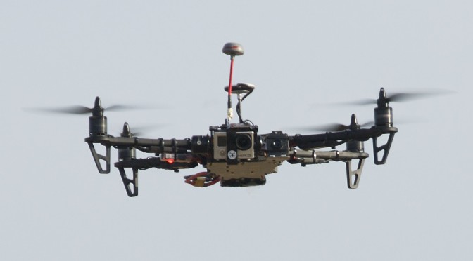
As we all know, my first TBS Discovery Pro crashed horribly with no hope for easy repair. So what should one do with all The FPV gear and not model to fly? Right. Build a second TBS Discovery Pro. It should not take too long, as I’ve documented my last build in detail (build log part1, part2 and part3). This time however I want to make some minor modifications:
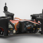
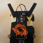
move the X8R receiver inside the frame next to the NAZA instead of having it sitting on the back outside.
repositioning of the video antenna to the top of the frame for better reception
Add RSSI connection for the OSD
Put the GPS puck on the stick for better reception
The 2nd TBS Discovery Pro arrived in a similar, but slightly lighter colored box.
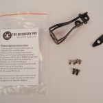
The new gimbal dampener arrived with the wrong number of screws. I should have some spare ones left from the last build.
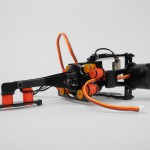
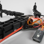
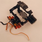
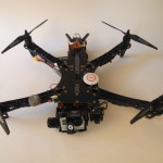
My 2nd TBS Discovery Pro came with the new improved gimbal dampening arm attached to the back. It should stabilize the camera at high speeds.
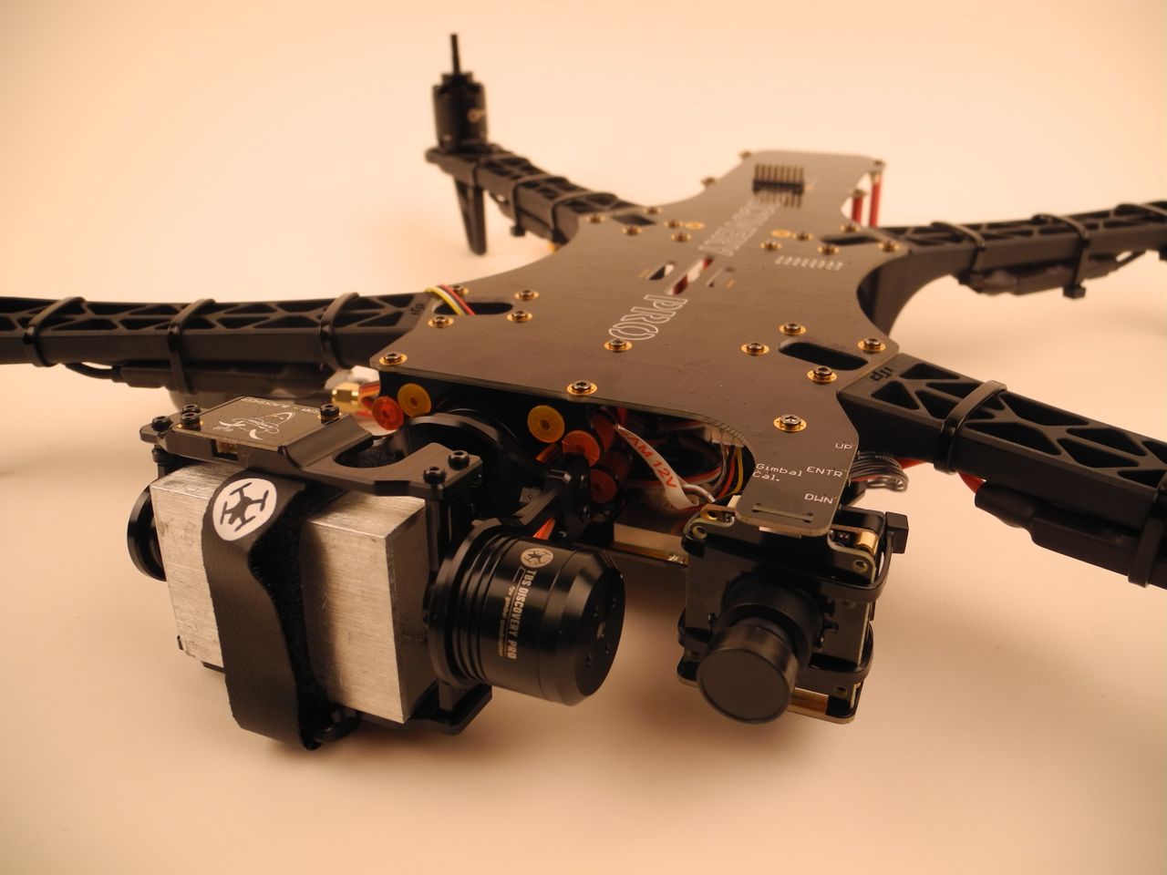
The new gimbal stabilizer will go deep into the frame, close the the NAZA in order to stabilize the camera rotational movements.
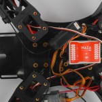
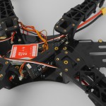
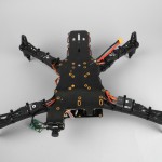
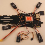
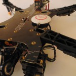
In order to fit everything, the NAZA controller is placed slightly forward outside the marked rectangle. This way, the edge of the X8R is just short of to the mounting hole for the red spacers which will later connect to the top plate.
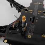
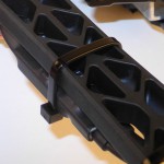
The X8R antennas can be zip tied to the arms. Both, the antenna and the arms, have a rounded shape which makes the placement relatively flush and solid. The zip ties keep them in place, minor movement is still possible.
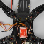
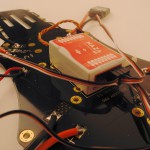
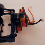
Closeup of the X8R lying sideways inside the frame.
Different angle of the frisky X8R placement inside the frame, flush to the NAZA.
The X8R is placed lying on the side, with the short cables going out to the antennas on the two arms.
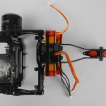
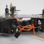
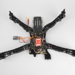
On my 2nd build, I’ve placed the video transmitter on top. TBS sells a special mount, which is not part of the kit and needs to be ordered separate.
Here I use a FLAME WHEEL VTX mount with a TBS 5.8GHz transmitter
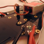
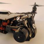
This time I’ve attached the NAZA LED IMU to the bottom of one of the ESCs.
On my second build I try to cram the X8R receiver inside the frame, next to the NAZA with the two antennas on the back arms.
The image gallery of the first build can be found here.
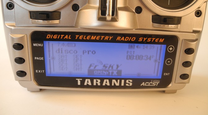
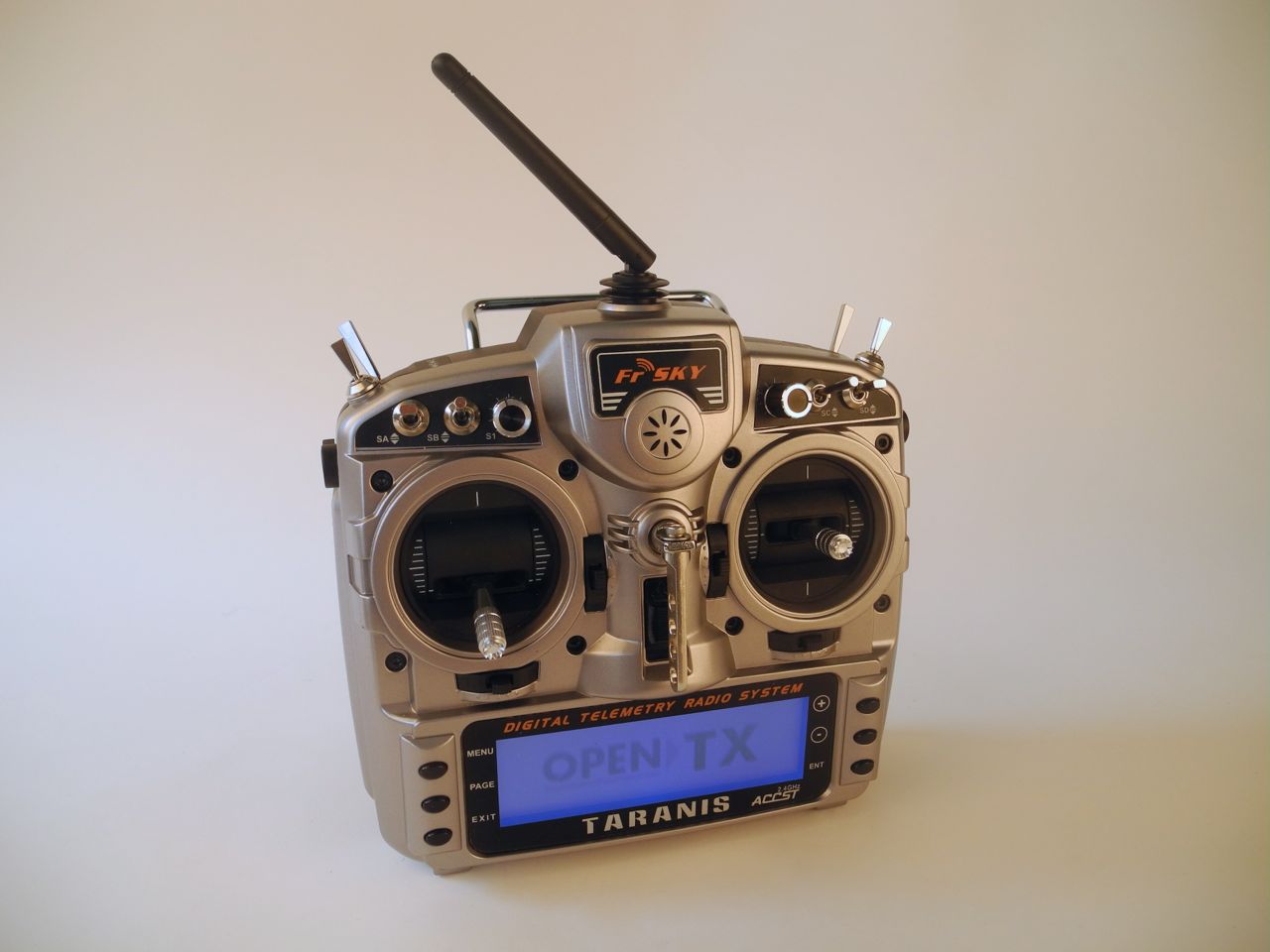
In the third part of the build log I would like to cover the setup and configuration of the Taranis RC with the TBS Discovery Pro. After covering the mechanical build in part 1 and part 2 of the build log, this part will be about the wiring and programming of the remote control. Due to a crash I’ve build the copter a 2nd time.
This is part 2 of the epic TBS Discovery Pro build. It got a bit delayed because I really wanted to show you the Leistkamm Video before finishing my second quadcopter. But now, back to the Discovery Pro.
After assembling the gimbal and motors and soldering the bottom plate in the TBS Discovery Pro build part 1, I put all the pieces together. It’s relatively straight forward to mount the four arms and red spacers to the bottom plate and then close up the sandwich with the top pcb plate. All the electronics and wiring is integrated into the frame and aside from the gimbal and controller, there are only a few cables connecting to individual parts. During the build I got to appreciate zip-ties for fixing all sorts of things, such as the electronic speed controllers (ESCs) onto the arms and the flight camera to the frame. The last piece I screwed on was the gimbal and it slides from the front.
Wrongly assembled gimbal. The tilt motor should face the other direction. Oooops!
At this point of the build I realized for the first time that something was a bit strange with the gimbal cables. I had to cross them to reach the appropriate connectors on the frame, which seemed a bit like a design flaw. But as it turned out later, I had misassembled the roll axis by 180 degrees, so the pitch motor facing the fpv camera instead of away from it. It took me until after the first power-up to realize this. The crossed cables lead to a second mistake: mixed up roll and pitch motors. The result of this is a hysterically spinning gimbal, rotating constantly as if were fully drunk. After fixing the gimbal orientation and connecting the motors into the correct pitch/roll connector everything was OK. The gimbal was level as expected. Wow, it looked cool!
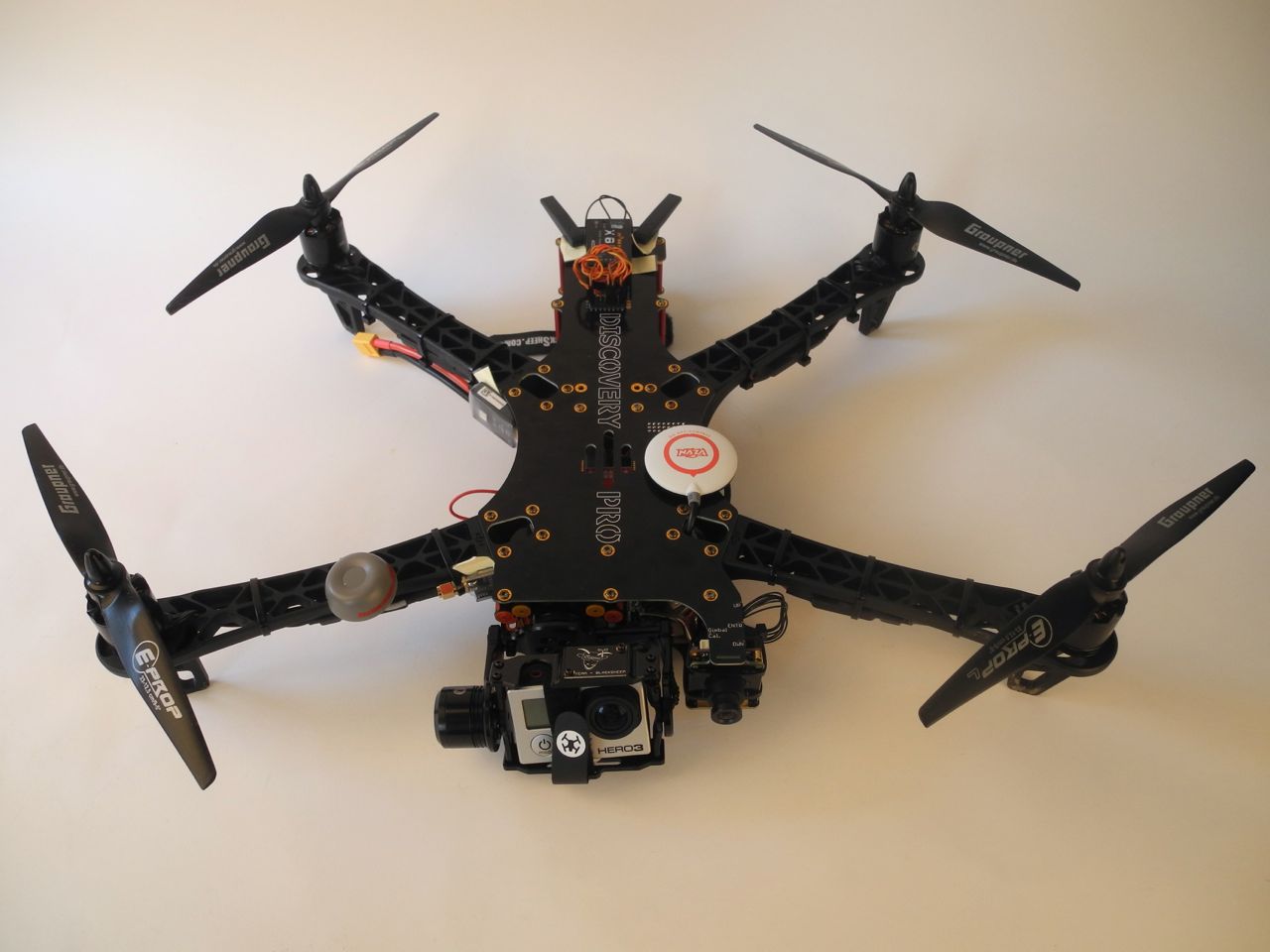
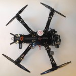
Fully assembled Discovery Pro
I finished the ‘mechanical’ part of the build by adding more electronics, such as the video transmitter with the 5.8GHz cloverleaf antenna on the front right arm and the FrSky RC receiver X8R in the back on top.
More images in the build gallery. In the next part of the build log I will set up the Taranis RC radio and NAZA flight controller.
Gimbal partial assembly with the two brushless motors and the GoPro cage
Disco Pro ground plate with Naza Light in the center and the dji power unit on the bottom
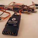
Close-up of ESC, TBS Bulletproof with SimonK firmware
Bottom plate of the Discovery Pro with the NAZA light flight controller and all four ESCs soldered and wired up. The Naza should better be placed further to the front of the copter. Otherwise the GPS cable (not shown on the picture) will stick out too far into the battery compartment.
Close-up of Naza light, connected with a single wire to the receiver, controlling it through s.bus.
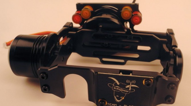
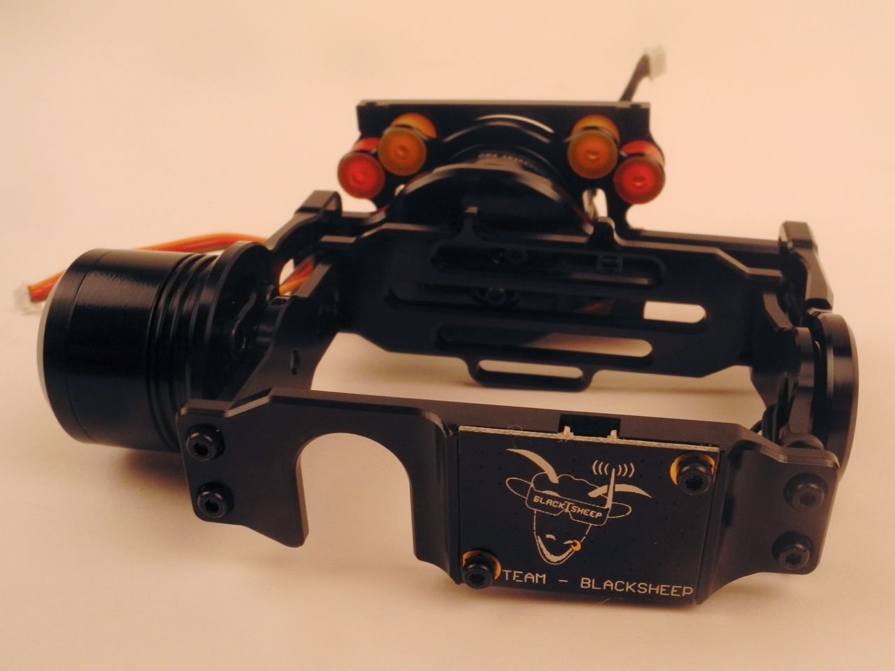
Fully assembled gimbal with dampers 180 degrees flipped around.
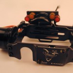
Fully assembled gimbal from the front.
Vibration dampers, red/orange as suggested by the build instructions.
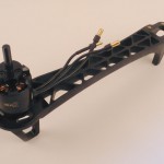
F450 flamewheel arm with Tiger 900kv Motor
Fully assembled Discovery Pro
Zip-ties holding the cables and ESC underneath the arm.
NAZA-M Light flight controller wired up inside the frame.
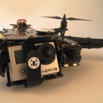
Flight camera in front with the pushbuttons for gimbal calibration and on-screen display settings.
Backend of the Discovery Pro with the FrSky X8R receiver and the two PCB antennas.
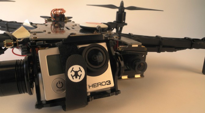
GoPro and flight camera of the TBS Discovery Pro.
Correctly mounted gimbal with the GoPro and the colorful dampers in the back.
Soldering iron, screwdrivers, zip ties, loctite 222 (the purple one)
I’ve started with the gimbal assembly, a big puzzle with motors, screws and aluminum parts. The small screws are for the metal parts and some of the short bigger ones (from a separate bag) are for the gimbal motors. The small electronic board was a little bit too big, but after grinding the board on two ends by fractions of a millimeter it fit snugly into the holder. Two tiny little grub screws are used to hold the tilt motor. One is not enough as I had to find out. The cables are attached with zip ties, which have to be attached exactly how the video shows. Otherwise the ends of the zip-ties collided with other parts, preventing the gimbal from turning freely. For the time being I chose the standard red and orange damper configuration. However, this might change as the dampers need to be fine tuned. There are reports of vibrations with the standard setup. All orange seems to be a good option too. I will have to test this out. [Update] The roll axis on my build is 180 degrees wrong and should be flipped around. While the GoPro cage is upright, the dampers are upside down. They should be forward on top and backward on the bottom for a push/pull configuration. [/Update]
Fully assembled gimbal from the front.
Next, I put the gimbal to the side and started with the frame by soldering the ESCs and the battery connector. I started out with a very fine soldering tip but this did not work and I had to mount a fatter soldering tip which could deliver enough heat. This was fairly easy. And I completed the work on the bottom plate with gluing the Naza flight controller with a 3M patch.
Disco Pro ground plate with Naza Light in the center and the dji power unit on the bottom
Last step of the today was assembling the Tiger 900kv motors. I removed all the screws on the prop holders and mounted them with loctite to the top of the motors. Then I found out that short silver screws and the cross piece in the package are not used. Instead the motors are directly bolted onto the arms with screws out of one of the bags. The quality of theses screws however gave me headaches. None of my standard screwdrivers had a tight fit. Finally, I used a hex key to tighten the screws on the arms. I did not use loctite for now, as the arms are plastic. But if they come loose I might have to reconsider this.
That’s all for the first part of my build log of the TBS Discovery Pro. So far I am positively surprised about how everything is designed (minus the screws). The official build video is sometimes a bit too fast and I needed to rewind it many many times. Stay tuned for the next part of the build!